Half Wave Bridge Rectifier Circuit Diagram Bridge Rectifier
Rectifier half output voltage principle Describe the half wave rectifier using a diode Full wave rectification diagram
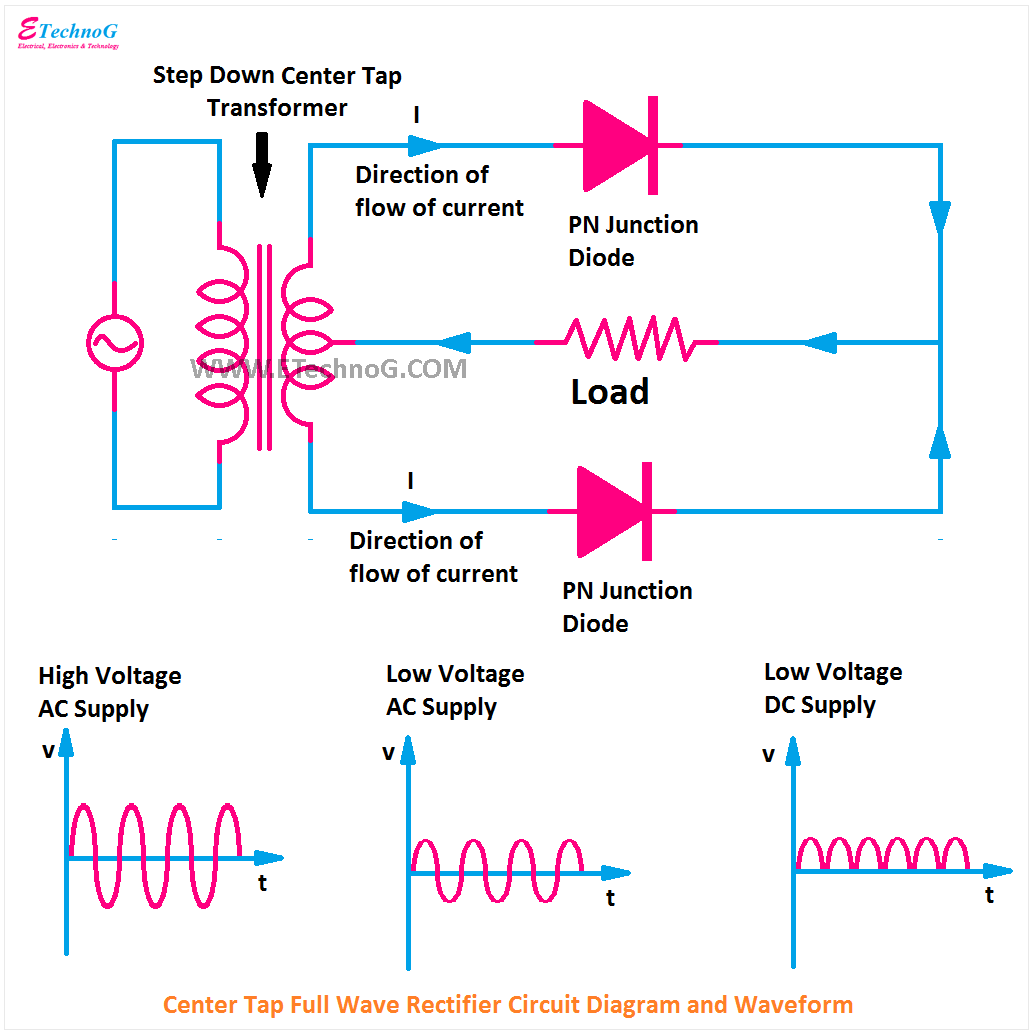
Half Wave & Full Wave Rectifier: Working Principle, Circuit Diagram
Full wave bridge rectifier circuit diagram Bridge rectifier diagram discount compare, save 44% Half wave bridge rectifier circuit diagram
Rectifier circuits diy working
How the half wave rectifier circuit works wiring view and schematicsHalf wave bridge rectifier circuit diagram Half wave & full wave rectifier: working principle, circuit diagramHalf wave bridge rectifier circuit diagram.
Full wave bridge rectifier schematicBridge rectifier wiring diagram Full wave bridge rectifier circuit diagramHalf wave bridge rectifier circuit diagram.

Half wave bridge rectifier diagram
[diagram] h bridge circuit diagramSimple bridge rectifier circuit Full wave rectifier bridge circuit diagramRectifier circuit diagram without transformer.
.


Half Wave & Full Wave Rectifier: Working Principle, Circuit Diagram

Bridge Rectifier Diagram Discount Compare, Save 44% | jlcatj.gob.mx

Full Wave Bridge Rectifier Circuit Diagram - Riset
![[DIAGRAM] H Bridge Circuit Diagram - MYDIAGRAM.ONLINE](https://i2.wp.com/theorycircuit.com/wp-content/uploads/2018/03/full-wave-bridge-rectifier-circuit-diagram.png)
[DIAGRAM] H Bridge Circuit Diagram - MYDIAGRAM.ONLINE

Half Wave Bridge Rectifier Diagram

Full Wave Bridge Rectifier Schematic

Describe the Half Wave Rectifier Using a Diode

Half Wave Bridge Rectifier Circuit Diagram
Full Wave Bridge Rectifier Circuit Diagram

How The Half Wave Rectifier Circuit Works Wiring View And Schematics